From woodworking to electrical engineering…
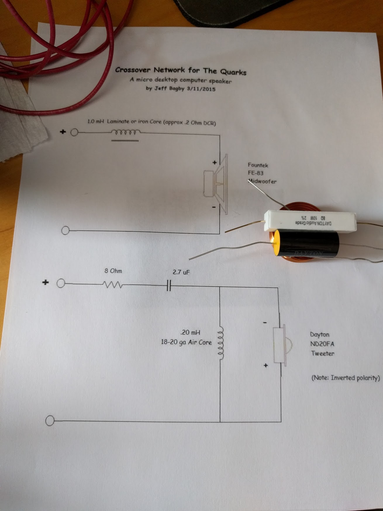
I have outlined some principles of crossovers as I understand them w.r.t. the Quarks design in a previous post. Here is how I actually assembled the crossover.
What Wire to Use?
Pretty much the only thing that does not come with the Quarks kit is some wire to connect all the crossover components, the drivers and the binding posts (which is where the external speaker wire gets connected) inside the speaker cabinet together.
This raises the question of what wire to use. We want stranded wire, which is comprised of multiple leads woven together because it is more flexible and will not break easily if we move it around. Also we want isolation on the wire to avoid shorts. The question that remains to be answered is how thick should the wire be?
Wire thickness is measured in something called “gauge”, abbreviated as “ga”. And to make things more confusing, smaller numbers mean a larger diameter. Here is a table that tells you what gauge corresponds to what wire diameter.
In order to determine what thickness would be appropriate, I took the capacitor that comes with the Quarks kit and measured the diameter of its leads with a pair of calipers. — Turns out they are 20ga, which is quite small, but we are building tiny speakers here.
So that gave me a ballpark figure. — Since I plan to use stranded wire, I decided to go up a little and to shoot for 18ga. I did not have anything near that at home, so I went to my favorite electrical supply store in SF. 16ga stranded wire was in stock. I ended up buying 6ft of it for less than a dollar…
Initially I thought that 6ft would be way too much because I only need a couple of pieces, where each piece is a couple of inches long but I ended up using all of it, which I did not expect.
Space Constraints
The Quarks are tiny, so laying out the components inside the cabinet is a little tricky. — Turns out I had made a mistake by drilling the holes for the binding posts in the back without looking at the crossover components first: The inductor that goes in series with the woofer is quite large and when I put it on the bottom inside the cabinet the binding posts don’t clear it. Had I moved the binding posts a little higher, this would not have been a problem.
Luckily the cabinet is deep enough so that you can put the inductor in front of the binding posts and you still have enough clearance to install the woofer.
The plan is to put the large inductor for the woofer in front of the binding posts and hot-glue all the crossover components for the tweeter together. This is a first attempt in laying this out. The inductor is the coil in the bottom. The capacitor is the black/yellow cylinder and the resistor is the white rectangular box):
Soldering
One thing you want to avoid when soldering is heating up the components you solder together too much, or you could cause damage. This is less critical with a crossover, but if you ever have to solder semiconductors (transistors/diodes) it becomes a larger issue.
Therefore you only want to touch the soldering iron to the wires for a couple of seconds and then give things time to cool off again.
This lead to an interesting observation: I first started out with a small 10W soldering iron and the results were really bad. The solder didn’t “flow” properly, presumably because the leads were big enough to wick heat away quickly and 10W was not enough to keep everything hot. This was especially bad when soldering the 16ga copper wire to anything. — Copper does conduct heat really well…
I had recently purchased a 60W soldering iron that was fairly cheap and I didn’t have much hope, but things improved quite a bit once I switched to this soldering iron. I could get the solder to “flow” and only had to touch the iron to the wire for a few seconds each.
How Long Did It Take?
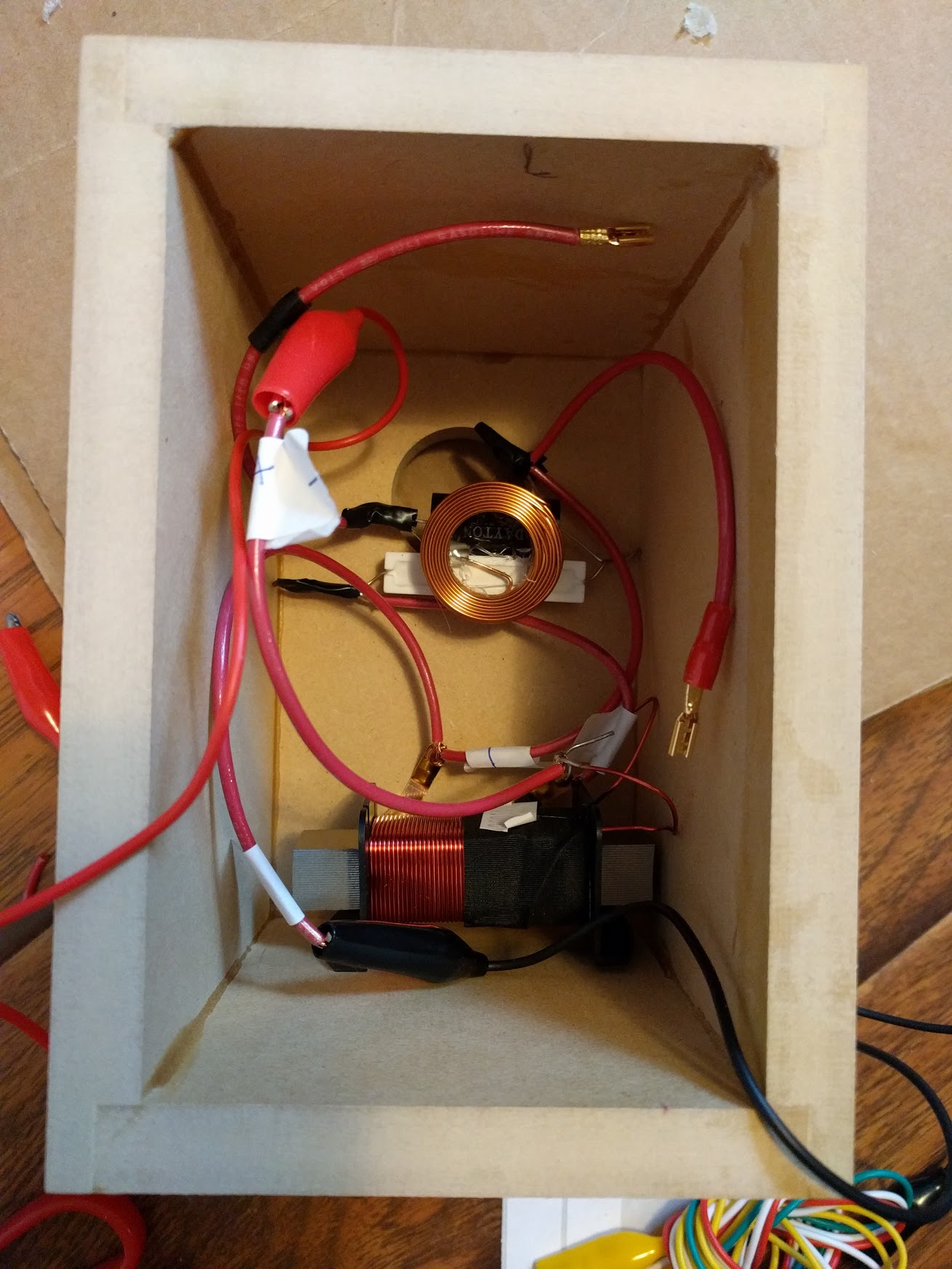
I didn’t time it, but getting the first crossover done took forever. Not the actual soldering, but I had to figure out a way to lay out things in the cabinet that would work, and determine wire lengths, decide whether I’d rather solder multiple wires onto the binding post terminal (which is what I did) instead of onto crossover component leads, and position things so that bare wires wouldn’t touch each other.
Also, I made little stickers to put on wires, to label what goes where…
After getting done with the first one, assembling the second crossover took almost no time.
The Result
Here is what I got eventually. Things are not glued into the cabinet yet, because I want to finish the cabinets first. The plan is to glue the large inductor in front of the binding posts, and the smaller inductor with the other crossover components already hot-glued on against the back of the cabinet, above the binding posts, but below the back hole for the port tube.
This looks more messy than usual also because I added some additional alligator clamp cables to the mix, in order to be able to test things out.:
Basic Testing
Basic crossover testing was done by connecting everything together and hooking up the speakers to a Topping VX2 class D all digital amplifier, which in turn was connected via USB to my Linux PC running Ubuntu 16.04. — Turns out that rumors on the internet that the VX2 causes havoc with the Linux USB stack were unfounded and things worked right out of the box.
I then went to http://www.onlinetonegenerator.com/ and tested a 440Hz tone, which is well below the crossover frequency. By getting really close to the speaker I could confirm that the tone was coming from the woofer and not the tweeter. Then I switched to 4400Hz, which is well above the crossover and I could confirm that the tone was coming from the tweeter this time and that the woofer remained silent.
So crossovers are working and so are all woofers/tweeters.